Electrical controls
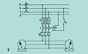
Beside are the connection diagrams for the Vical A® feeder troughs. The circuit in 1 presents the usual connection in which the following details are presented:
Protection device that encompasses the fuses e and the adjustable thermal relay el. Interchanged is the switch c operated by the control circuit Cc for automatic or manual controls. It is important to note the direction of rotation of the vibrators V (one opposite the other) because without this precaution the feed chute will not function properly.
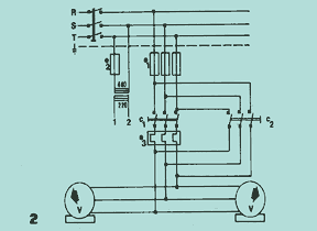
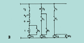
Diagram 2 shows the circuit for counter-current braking. In general, vibrating machines have large beats when switched off, because the V vibrators pass through critical speeds when slowing down. To eliminate these vibrations, the free rotation time of the vibrators is reduced by means of counter-current braking. Control circuit 3, guided by time relay d2, injects counter-current through switch c2 for a period of 2 seconds.
The counter-current is produced by allowing switch c2 to reverse the supply phases (RST). This type of circuit is very useful for vibrating machines that do not work continuously but only for a few moments, in rapid sequence.
Vical A® vibratory feeders can come equipped with frequency inverters for capacity regulation from 0 to 100%.